Learning CenterWhat is a mineral?The most common minerals on earthInformation for EducatorsMindat ArticlesThe ElementsThe Rock H. Currier Digital LibraryGeologic Time
搜索矿物的性质搜索矿物的化学Advanced Locality Search随意显示任何一 种矿物Random Locality使用minID搜索邻近产地Search Articles搜索词汇表更多搜索选项
╳Discussions
💬 Home🔎 Search📅 LatestGroups
EducationOpen discussion area.Fakes & FraudsOpen discussion area.Field CollectingOpen discussion area.FossilsOpen discussion area.Gems and GemologyOpen discussion area.GeneralOpen discussion area.How to ContributeOpen discussion area.Identity HelpOpen discussion area.Improving Mindat.orgOpen discussion area.LocalitiesOpen discussion area.Lost and Stolen SpecimensOpen discussion area.MarketplaceOpen discussion area.MeteoritesOpen discussion area.Mindat ProductsOpen discussion area.Mineral ExchangesOpen discussion area.Mineral PhotographyOpen discussion area.Mineral ShowsOpen discussion area.Mineralogical ClassificationOpen discussion area.Mineralogy CourseOpen discussion area.MineralsOpen discussion area.Minerals and MuseumsOpen discussion area.PhotosOpen discussion area.Techniques for CollectorsOpen discussion area.The Rock H. Currier Digital LibraryOpen discussion area.UV MineralsOpen discussion area.Recent Images in Discussions


Mineral PhotographyAmscope...

5th Jan 2012 02:48 UTCSteve Sorrell Expert

Today I received a package containing two items. A microscope adaptor for my Canon 600D (AmScope CA-CAN-SLR) and a 9Mp microscope digital camera (AmScope MU900).
I have just done a couple of comparison shots and there is (understandably) a huge difference in quality. I think that although I will use both, I will focus much more on the adaptor.
The Canon plus adaptor is far superior to the MU900 wrt:
<*> Depth of field
<*> General crispness
<*> Colour balance (I use an LED ring light)
The MU900 will be useful seeing that I can connect directly to my laptop and has a slightly wider field of view.
Also, something that I found interesting, the MU900 gives you a mirror image. Not a real problem as it is easy to flip with software, but you wouldn't necessarily notice unless you had something like letters or numbers. I only noticed because I was comparing two photos taken using different methods. I suppose I would have eventually realised!
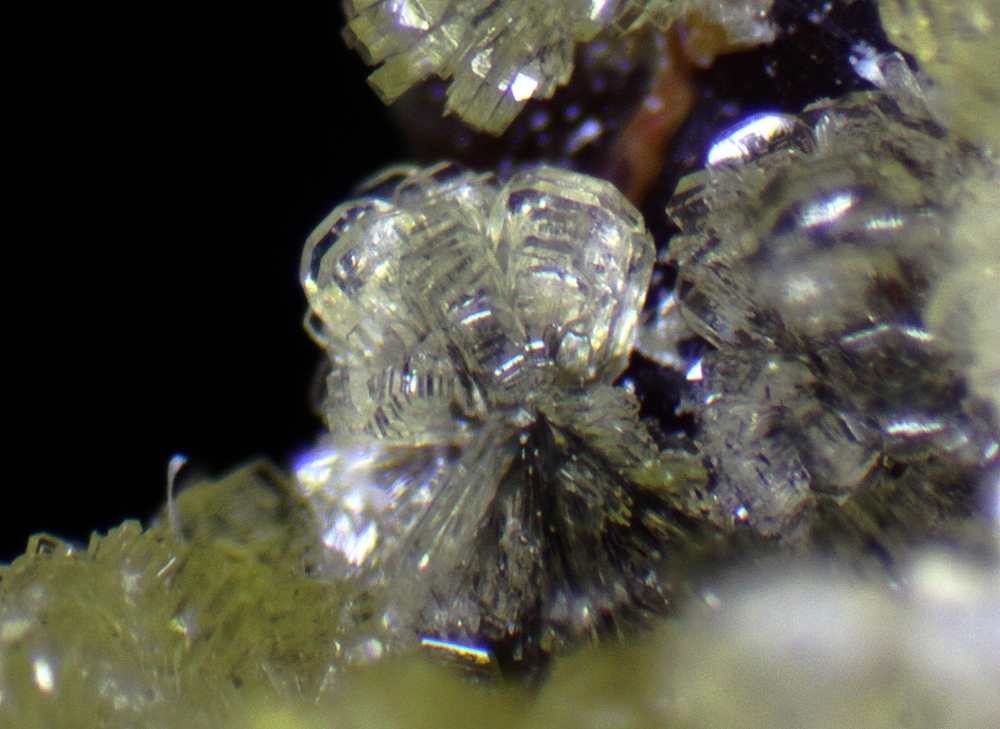
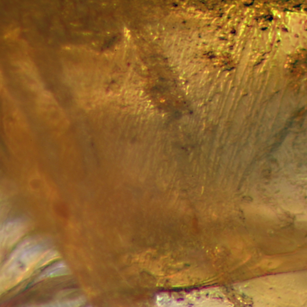
Anyway, here are two photos of a barite after alstonite from Nentsberry to show the differences. The first is the MU900 (after reversing the image!), the second using my Canon.

Regards
Steve
5th Jan 2012 02:51 UTCSteve Sorrell Expert


Regards
Steve
5th Jan 2012 06:11 UTCSteve Sorrell Expert
Here's one after I've played around a bit...
Regards
Steve

5th Jan 2012 08:09 UTCRick Turner
I find that the most useful thing about attaching an SLR (I am using a Canon 7D) to a scope is that you can more easily control the aperture (and thus depth of field) and white balance. The numerical aperture of an SLR setup is usually better than for a dedicated camera too.
Downside of an SLR is that it's harder to see the image that you are going to get beforehand, at least without getting a crick in the neck, and it can be harder to adjust the mount so that the focal plane of the camera is coplanar with the focal plane of the microscope optics. If the two are not the same, the camera image is out of focus with respect to the microscope image, so it requires fiddling around, but also can introduce aberration of various kinds - I find that colour fringing (chromatic aberration) and intensity ringing are usually the most noticeable.
By comparison, I find that a dedicated scope mounted camera (I have a Lumenera Infinity 2) is better for taking sequences of images, so I use that for EDF work. It's also less likely to cause vibration (the mass at the top of the scope is much less than with an SLR) so is better suited for high magnification work - I have been imaging crystals down to about 10 microns in size with this setup quite successfully (some of these images are on Mindat - fornacite and mereheadite xls).
At the moment I am trying to find an e-mount adapter for a microscope - I have a Sony NEX-7 and want to try this out as a scope camera. If it works, it should be superb - better than an SLR in many ways. It has an APS-C sensor (so 24 MP) but is about 20% the size and weight, and has 'anti-vibration' and HDR capability in the body. It also has a tilt/swivel screen on so no more sore neck!
Regards
Rick
5th Jan 2012 10:04 UTCSteve Sorrell Expert
<*> 600D has a tilt/swivel screen with the ability to zoom in to focus - which is good
<*> No ability to set the apeture - it shows as F00 and I can't override - so stuck with what I get. Mind you the DoF is not bad.
<*> Canon camera body is not that heavy, so little strain - which is good
Regards
Steve
11th Mar 2012 19:05 UTCRick Turner
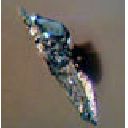
I'll attach an image to this post as an example - the wulfenite xl is about 3mm square.
Rick

12th Mar 2012 00:48 UTCReiner Mielke Expert
Can the Sony NEX-7 feed a live image to a computer that can be captured by the computer?

12th Mar 2012 02:47 UTCEugene & Sharon Cisneros Expert
If you are not already aware of it, Cannon EOS Utility software gives you the ability to view the image live on your computer monitor. I use it with my D7 and find it to be the best way to focus and control the camera settings remotely. Also, you can lock up the mirror and use the electronic first curtain shutter to eliminate virtually all vibration.
Rick, I am wondering why you say that the aperture is easier to control. Are you using the camera lens in an afocal setup? In any case increasing depth of field by reducing NA always results in less resolution. Nice shot of the Wulfenite, no problem with resolution there! What combination of camera and microscope did you use?
I just got first light in my new setup, using the 7D, last week and am still sorting out problems. But, here is one of my first attempts. Neptunite at 2mm FOV.
Gene
12th Mar 2012 03:21 UTCHenry Barwood
12th Mar 2012 05:56 UTCRick Turner
The wulfenite picture is taken with a Sony NEX-7 fitted to a Wild M7A scope. There is no lens on the camera - I have (made) an adapter to fit the camera to a standard C mount thread, which allows me to fit it to any of my scopes using their standard phototubes etc. Simplest possible solution that I could think of, and means that I dont need to change any of my other gear.
I have tried with my Canon 7D as well but with less good results - actually, I prefer the Sony for lots of reasons.
Reiner: I have not tried to do live feed from the NEX-7 to a PC, sorry.
Rick
12th Mar 2012 15:54 UTCEugene & Sharon Cisneros Expert
It looks like you have a winning combination, and I look forward to seeing more images.
Henry,
The image of the Neptunite is a stack of 26, processed with CombineZ. Unfortunately, the immutable laws of physics never provide for a free lunch. That image should have been more like a stack of 50, but for testing I have been keeping the stacks to a minimum.
Gene
12th Mar 2012 23:37 UTCReiner Mielke Expert
How did you make an adapter and where did you get the parts? I am thinking of getting a Sony NEX-7 and want to make sure I can adapt it to my scope.
13th Mar 2012 06:19 UTCRick Turner
I literally made it - I have an industrial CNC lathe and a big CNC mill in my garage (I build 5 inch gauge live steam locomotives) - so I machined my own from a bit of aluminum bar that I had lying around.
Sony dont make a c-mount adapter.
Rick
13th Mar 2012 17:12 UTCEugene & Sharon Cisneros Expert
13th Mar 2012 20:01 UTCReiner Mielke Expert
14th Mar 2012 00:52 UTCOwen Lewis
Congrats on choosing the 600D. It's a great camera for both macro and micro work I think. As the swing-out, rotatable LCD view (with the option of x5 or x10 mag for critical focussing) makes for a comfy life and a less cluttered bench as one does not need to compose on a PC screen.
I bought mine around Xmas time and have spent most of the time since then finding how to wring the most out of it in macro work (with the 2.8 60mm EFS lens. Only in the last week have I bent myself seriously to finding out how to wring the most out of in in photomicrography. I seem to be battling with severeal issues but none are camera related,
The prime issue is that I can't get the same image crispness in the camera that I do when viewing through the eyepieces.The likely culprit here is the relay lens in the adapter, since that is the only piece of glass between the prisms in the pod and the CCD sensor. At the moment, having also first calibrated the 'scope, I'm running up a series of test images with a stage micrometer (0.01mm graduations with the division markers having an estimated width of about 0.002mm) before going into bat with the camera adapter supplier. Since the relay lens is an x1, to my simple thinking, it should be possible to have it taken out and attain an image in the camera of a quality determined by the microscope optics alone (i.e. equal to or better than that I ger when viewing through the eyepieces.
Other useful features in the 600D that are useful for micro work (if you haven't found them already) are:
- Make sure to set the camera to swing up the mirror when you start live view, so that at (remote) shutter release vibration is much reduced.
- Fix the dimensions of your images to 1:1 rather than the more usual 16:9 or 4:3. For photomicrography, I think that a square image is generally more useful (less post-camera cropping), making the best use of the microscope's circular field of view..
- Set the camera to show gridlines. (dividing your now squared frames into 16 smaller squares. This helps with composition and also gives one a crude graticule for assessing FOV and the size of objects in the image at any level of microscope zoom (if you've made up a calibration chart first).
Here's a series of pics that show the current state of play.
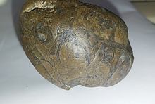
1. This is a cropped macro shot of a pink octahedral Spinel holding an 'alien' yellow octahedral Spinel about 1/10th its volume. The pink crystal is about 3.8mm 'on the square'.
2. The same specimen, imaged with a cheap-ish 2MB digital eyepiece camera adapted to shoot through the scope's trinoc port. Nominal x10 magnification
3. The same stone imaged with the 600 D using the adapter bought for it to fit on my pod. Magnification x62. Worked on with the unsharp mask and light source adjustment.
Edit:
Ooops! wrong shot for 3. Now corrected.
Glad to find another 600/600D user here :-)
14th Mar 2012 06:20 UTCRick Turner
Rick
26th Mar 2012 11:09 UTCSteve Sorrell Expert

Thanks Owen for the tips, so much I haven't even found, let alone tried yet.
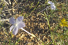
Here's a close up shot that I did a couple of days ago...
Will get back to micros in the next day or so.
Regards
Steve
26th Mar 2012 19:17 UTCOwen Lewis

That's very pretty - and a lovely specimen too :-)
Yesterday. I decides to sit down and quantify properly my perception that my microscope + camera adapter does not deliver the same image resolution to my 600D sensor as the microscope alone does to my eye retina. The results were unexpected and a little humbling.
The test was made by taping a stage micrometer slide to the microscope's stage (designed for gemmological usage). The slide has on it a 1mm graticule subdivided into 10 divisions, each division being subdivided into ten smaller divisions of 0.01mm each (including the width of one of the dividing markers). By observation, the dividing markers and the spaces separating them when viewed most clearly at high magnification at approximaely equal, suggesting a marker width of about 0.005 mm (5 microns).
Images were viewed with the naked eyball in the usual way through an eye-piece and also imaged in the 600D body mounted via its adapter to the trinocular port. Viewing and imaging was done at every x5 magnification step from x10 to x62. Results and conclusions were as follows.
1. Resolution by the microscope's optics varies with the magnification level set. At x10, the limit of resolution of my instument is about twenty microns (0.02mm). At x20, the resolution is just about 10 microns. As magnification increases further so does the resolution. Interpolation indicates that at x65 the resolution is close to 1 micron.
2. These results hold true both for eyeballing and camera imaging. However, by 'naked' eyeballing the image being produced in the microscope at all mag levels is *perceived* to be sharper, though in truth the resolution is no better! How can this be? I reason as follows:
- The field of view of the microscope is 23mm at 10, reducing to 3.7mm at x65 (nom). These manufacturer's specs were earlier verified in another series of tests.
- However, through the camera adapter the sensor plate is presented (square view) with an FOV of just under 5mm at x10 reducing to about 0.75 mm at x62.
- This amounts to approximately x5 'empty magnification', i.e. looking x5 bigger but with no improvement in resolution to go along with it. Ergo, the fuzziness at sharp edges caused by the laws of optics and the microscopes design limits is simply multiplied up by x5, giving the appearance of worse resolution (by about a factor of 5! :-( This is the same effect as obtained by increasing the magnification range of a zoom microscope by doubling of tripling the magnification of the eyepieces.
- This is something I should take up with the adapter manufacturer. Assuming a square image capture (the most efficient match to the circular FOV of a microscope), ideally, image size in each should be the same at any microscope setting.
- Making the linear FOV presented to the camera about 1/5 of the microscope's FOV results in several disadvantages, an apparent loss of sharpness being but one!
3. Another and very unexpected result is that resolution is better when the target was (low level) brightfield illuminated (appearing dark on a light background) was much clearer (better resolution) then when illuminated with overhead lighting, which also creates some strange chromatic aberrations. I propose to re-run this second set of tests, varying the intensity of the ilumination to determing the optimum and then see if there is still any difference in the quality of the imaging.
Meantime, here's a pic of a part of the stage micrometer taken at x65 zoom. Original file is at 3456x3456 pixel definition, reduced here to 800x800
Not as pretty as yours, Steve - but I lead a sad life :-)
27th Mar 2012 23:19 UTCEugene & Sharon Cisneros Expert
By calculation, at 62X, you should have a horizontal field of view of ~3.6mm on an APS-C sensor, if your relay lens is indeed 1X. If you measure 0.75mm, then something is definitely wrong. I am assuming that there are no other optics between the relay lens and the sensor. Have you tired removing the relay lens and projecting directly onto the sensor? Depending upon the microscope optics, the relay lens may be necessary to correct field curvature, or even chromatic
aberration. This is because, in some microscopes, the final correction is done in the eyepieces.
I look at the aspect ratio issue from a different perspective and always run at sensor’s native aspect ratio. My reasoning is this. Many objectives will fully illuminate an APS-C sensor (see attachment). So, the notion of best matching to a circular field doesn’t enter into my thinking. It is the circular field that is actually cropped by the sensor. I want to capture all of the information that is possible and then crop out what I don’t want later. This is especially important in stacking because of the spatial drift of each image in the stack with respect to the last. These artifacts have to be cropped out after processing, which further reduces effective sensor area.
Gene
28th Mar 2012 00:06 UTCEugene & Sharon Cisneros Expert
I forgot to mention that I have never known of anyone who thinks that they get better resolution from the camera than from the good old eyeball. To be fair, when comparing the view through the eyepiece with that of a captured image, it must be compared at the same scale. This is not easy to do, as the eyepiece view is measured in apparent angle of view, which means that the digital image must be compared at a distance where it has that same apparent angle of view.
Gene
28th Mar 2012 04:23 UTCOwen Lewis
Mineralogical Research Company Wrote:
-------------------------------------------------------
> Hi Owen,
>
> By calculation, at 62X, you should have a
> horizontal field of view of ~3.6mm on an APS-C
> sensor, if your relay lens is indeed 1X. If you
> measure 0.75mm, then something is definitely
> wrong.
Can we look at that for a moment? I'm thinking that the circular FOV is ~ 3.6mm and that's what my measurements seem to show, roughly supporting the manufacturer's spec. If that is so then only about one third of the FOV area (pi * (3.6^2)) is focussed onto the APS-C sensor? This is an important foundation to where I think I need to be going - so I had better have it right! :-)
> I am assuming that there are no other
> optics between the relay lens and the sensor.
That's what I'm told (and think I can see). But the setup is delivering ~ x5 of 'empty' magnification. of which about sqrt 2 'mag' is accounted for by the cropping of the FOV falling on the sensor.It further seems that if I opt to utilise only the central square 3456x3456 pixels of the sensor, then a x0.5 relay lens should just about maximise the amount of the scope's FOV that can be captured on the 3456 pixel square. Make sense?
> Have you tired removing the relay lens and
> projecting directly onto the sensor? Depending
> upon the microscope optics, the relay lens may be
> necessary to correct field curvature, or even
> chromatic
> aberration. This is because, in some microscopes,
> the final correction is done in the eyepieces.
I'm not equipped to drop the lens out. I don't believe that with this pod (a MZS 1065T, which is closely similar in design and build to the more common MZS 1045 (T)) that correction for field curvature and chromatic aberration at the final stage (eye-piece/relay lens) is a requirement.
> I look at the aspect ratio issue from a different
> perspective and always run at sensor’s native
> aspect ratio. My reasoning is this. Many
> objectives will fully illuminate an APS-C sensor
> (see attachment). So, the notion of best
> matching to a circular field doesn’t enter into
> my thinking. It is the circular field that is
> actually cropped by the sensor. I want to capture
> all of the information that is possible and then
> crop out what I don’t want later.
Agreed. However, isnt photomigrography a special case, in that the MP count of modern cameras is way ahead of anything that the resolving power of an optical microscope can utilise? From memory, 5 MP is about the optimum effective pixel count for photomicrography, above which one simple gets over-sampling. Which is why USD **** digital cameras purpose-designed for optical photomicrography (which no DSLR is) so often have a surprisingly low pixel count and yet can produce marvelous photomicrographic images?
The 600D's sensor is 18 MP. If I choose to work with a square format that is reduces to ~12MP (useable), even then I have a margin in hand (and still some image over-sampling).
> especially important in stacking because of the
> spatial drift of each image in the stack with
> respect to the last. These artifacts have to be
> cropped out after processing, which further
> reduces effective sensor area.
One thing at a time Gene... one thing at a time. First I need to optimise the resolution of the recorded images. Then I'll turn to other issues :-) For the while, I just experiment with some simple stacks (and early results are encouraging). Since my interest is in gem crystals, my stacks are mainly confined to just a few millimetres of Z axis. But one thing at a time. Until I've got the resolution is maximised, all else will be building on sand.
So, returning to microscope resolution (especially in Greenough stereo zoom designs) do you have any micrometer images that show the resolution capabilities of one or more other makes/models of microscope - or know of a web link where such can be found? I'd like to be as well armed as possible before beating up on the adapter manufacturer to rectify the unit sold to me.
Similarly, if anyone would like my complete set of micrometer images, to make comparisons of their own I'd be very happy to supply.
Owen
28th Mar 2012 06:23 UTCOwen Lewis
Our exchange is out of synch - but we'll manage. Your after thought is a good one (but I certainly don't look for *better* resolution in camera over eye - just, near as dammit, as good.
To the rest, can we come at it from a different direction?
From your diagram, in a properly set up rig, the scope's diametric FOV is the same length as the as the distance between diametrically opposed corners of a rectangular full frame sensor and some mathematically-determinable greater length than the slant range across an APS-C sensor. It follows that if, at any handily chosen mag setting for the scope, the full 1.00 mm of the stage micrometer covers the same proportion of the slant range across a full frame sensor as it does of the scope's diametric FOV then the two observations, eyeball and camera are identically scaled. To do the same with an APS-C sensor one simply has to apply a fixed factor to compensate for the differently sized sensor area.
So what one wants from the image transfer from scope to camera is an arrangement that, for known dimensions of a sensor plate will, at any scope's magnification setting, cause a known length (say 1mm) to represent the same fraction of the slant range across the sensor as it does across the microscope's field of view.
So what's the compensation factor to be applied in reducing the microscope image to fit optimally to a APS-C sensor? If one opts to utilise only the centre square of the sensor plate, then the slant angle to which the micrometer scale must be aligned for testing is 45 degrees to the horizontal. And what one wants, it seems to me, from one's camera adapter (beyond a sturdy physical mounting for the camera) is an arrangement whereby the microscope's FOV is reduced according to the following formulae:
X = 2*L/3 where X is the side of the square on the sensor to be utilised and L is the length of the APS-C sensor
then:
R = X/cosine 45 where R is the slant length across the square.
So, if you can tell me the dimensions of an APS-C sensor in millimeters we'll have a working basis on which I can go away, make a fresh set of observations (at a 45 deg slant) and re-calculate the misalignment of my present set up from the ideal. It's been a long night here but not a wasted one for me I think. A clear step forward which would not have been taken (at least as quickly) had you not chipped in, Gene.
Thanks,
Owen (now edited to correct 'schoolboy' maths error :-)
28th Mar 2012 23:13 UTCEugene & Sharon Cisneros Expert
Strangely, various manufacturer's APS-C sensors are not all the same size. Canon's APS-C sensors are 22.2mm X 14.8mm.
The diagram that I included in my last post was just to illustrate the relative geometry of sensors superimposed on the Microscope's FOV on the image plane. The relative sizes are not necessarily correct for a given objective. Some objectives will more than cover a full frame sensor and some will not. Most will, fully illuminate an APS-C sensor.
My thinking is to forget what you see through the eyepiece. The eyepiece only covers a portion of the actual FOV at the image plane (or sensor). Further, we don't use the eyepiece for photography, so why consider it?
My goal is to get as much of the subject of interest onto the sensor. That optimizes the use of sensor area. So as not to confuse matters even more, I won't mention Nyquist sampling now. So, what is the scale factor for the situation above? Lets take a look at your microscope. I believe that it has a range of 10X to 62X when using 10X eyepieces. So, the zoom objective by itself has a range of 1X - 6.2X. For example, using the highest magnification of 6.2X, we divide the horizontal dimension of the sensor by 6.2. So, 22.2mm / 6.2 ~ 3.6mm is the field width. That is, the image plane (or sensor), will see 3.6mm of the object plane. Of course, if your objective lens cannot fully illuminate the sensor, then the above is not applicable.
I'll stop here to see if this makes sense, or if I should lay off of the Margaritias.
Just for fun, and to keep in touch with the spirit of these discussions, I have added a recent Apatite image from my new setup. The field of view is approximately 1 mm wide. There is still plenty of room for improvement, but for now this is my best effort at this image scale.
Gene
29th Mar 2012 21:54 UTCEugene & Sharon Cisneros Expert
There was so much in your previous post that I am addressing it point by point, as I have time.
Agreed. However, isnt photomigrography a special case, in that the MP count of modern cameras is way ahead of anything that the resolving power of an optical microscope can utilise? From memory, 5 MP is about the optimum effective pixel count for photomicrography, above which one simple gets over-sampling. Which is why USD **** digital cameras purpose-designed for optical photomicrography (which no DSLR is) so often have a surprisingly low pixel count and yet can produce marvelous photomicrographic images?
Actually, for a given objective, it is the size of the pixels that determines Nyquist sampling rate, and not the total number of pixels in the sensor. Think of it this way. If your smallest resolvable feature, on the image plane, is X um in extent, then you would need at least 3 pixels to cover the feature for critical sampling, so each pixel would need to be X um / 3 in size . Because of the Bayer filter, it takes ~3 pixels, rather than 2, to satisfy the Nyquist sampling theorem.
Example: You have an objective that is 5X and has a resolution of 3 um. On the image plane, the smallest feature of 3 um would be 3 um X 5 = 15 um in extent. Therefore, a pixel size of 15 um / 3 = 5 um would give the lowest sampling rate for maximum resolution on the image. The Canon 18MP APS-C sensor has 4.3 um X 4.3 um pixels, a sampling rate of ~3.5, so is just about ideal. An eyepiece camera with 14MP has 1.2 um pixels and for this example would have a sampling rate of ~12, which is far from ideal. On the other hand, a 1.3MP eyepiece camera has 3.6 um pixels and has a closer to ideal sampling rate. With the assumed objective, this would do very well, but at a reduced field of view due to the small number of pixels.
So, if the pixel size is set for best sampling, then the number of pixels just determines the amount of FOV captured. A small sensor and a large sensor, at the same sampling rate will have the same resolution, but the fields covered will be different. The limit on the maximum number of useful pixels then is a function of your objectives usable coverage at the image plane.
One last comment. If you consider one of the high quality objectives like a 4X Plan Apo with NA=0.2 and resolution of 1.6 um, the sampling rate using the Canon APS-C is 1.56, clearly under sampled. The camera is limited in this case. To get the highest resolution images, the objective must be properly matched to the objective lens.
I'll need another Margarita before I think about the rest of your post. :)
Gene
29th Mar 2012 22:53 UTCOwen Lewis
I spent some time yesterday reading up on sensors. Cutting a long story short, my experimentation of last weekend may well have been 'moon-beam chasing' and needs to be done again from the beginning. The bull points seem to be these:
- The crispness obtained in a captured image depends on only on the resolution obtained by the microscope and delivered (as undiminished as possible) to the object plane but also on the algorithmic processing of the small electrical signals created in the sensor's pixels. I may well be inadvertently degrading the resolution obtainable by over-processing of the sensor data through selecting to employ routines such as noise reduction.
- I need to get some definitive answers re. the match/mismatch of my camera adapter's lens view to the Canon APS-C sensor plate dimensions. This with a view to optimising the match if necessary and possible. The images I made on Sunday actually don't help with this, though it was a useful little self-training exercise and providing a reference set, against which similar images can be assessed for any improvement in resolution.
So, before spending more camera-time in creating new images concerned with obtaining the best resolution, I think I need first to correct or confirm my present understanding of what is the optimum match between the 'lens view' and image captured on the Canon APS-C (non-standard size) sensor plate. Which brings me to responding to your thought provoking last post.
Mineralogical Research Company Wrote:
-------------------------------------------------------
> Hi Owen,
>
> Strangely, various manufacturer's APS-C sensors
> are not all the same size. Canon's APS-C sensors
> are 22.2mm X 14.8mm.
That's what I read too. Whether those are the physical dimensions of the plate or the dimensions of the actual pixel area I can't find. Anyway, apart from noting that this may account for some minor level of discrepancy between theoretical calculations and practical observations, one can let it go for now.
> The diagram that I included in my last post was
> just to illustrate the relative geometry of
> sensors superimposed on the Microscope's FOV on
> the image plane. The relative sizes are not
> necessarily correct for a given objective. Some
> objectives will more than cover a full frame
> sensor and some will not. Most will, fully
> illuminate an APS-C sensor.
I understand. But the camera manufacturer designs his lenses and bodies to get consistently close to a best matching of lens view to a full frame sensor's dimensions. In the case of some 'Brand X' microscope optics being used instead of one of his own nice lens units, then, as you say, what the optical train in the 'scope presents to the camera's sensor may or may not be well fitted to the camera manufacturer's 'lens view''. If there is a gross mismatch in coverage, the selection and use of an appropriate relay lens in the camea adapter might well improve the match. Does that seem fair and correct - thus far?
Turning then to a Canon camera using the APS-C sensor. This is substantially smaller than a full frame sensor plate. This in turn has the effect of cropping the 'lens view'. Canon publishes this 'crop factor'/focal length multiplier/empty magnification (all three terms referring to the one same effect) as 1.6. I take this to mean that, taking the corner to corner diametric distance of an APS-C sensor as being 1, on that same scale, the diameter of the lens view will be 1.6. In other words the lens view captured on the sensor plate is cropped linearly by about 1/3rd as a result of the physical dimensions of the sensor plate. That seem correct to you?
> My thinking is to forget what you see through the
> eyepiece. The eyepiece only covers a portion of
> the actual FOV at the image plane (or sensor).
> Further, we don't use the eyepiece for
> photography, so why consider it?
It's important (to me) only that, in a perfect world, I would want my camera to record as closely as possible the image I see through an eyepiece. This is a wish only. My intent is to find out how close to that I can get with the instruments I have.
> My goal is to get as much of the subject of
> interest onto the sensor. That optimizes the use
> of sensor area.
Ditto to the first part.
To my thinking, the second introduces a conflict of interest. Let's agree for a moment that potential image quality is maximised by utilising the entire sensor plate (rectangular area). But more of a circular field of view can be captured on a square snug-fitted to the circle circumference than can be captured in a rectangle of any other dimensions. So why don't camera manufacturers use square sensor plates? Two reasons I'd suggest:
- The 'letter box' has a smaller area, therefore fewer pixels and therefore saves them money.
- A large majority of the public prefer to frame their pictures as rectangles (there are good aesthetic reasons for this). Accordingly, providing them with a square (or even circular) sensor area that they would only choose to crop away anyway could not make economic sense.
However *if* one allows that modern pixel counts are actually not useful for photomicrography (pace 'stacking' concerns) because of the resolution limitations on objective lenses, one comes to my line of thought which is to:
- Utilise only the central square part of the APS-C sensor (the design of the camera firmware permits this). This effectively reduces the useful pixel count from 18 MP to 12 MP (still more than is necessary for photomicrography) but puts in place the basis for a maximum capture of the 'lens view'.
- Employ a reducing lens as the relay lens in the camera adapter to match as closely as possible the lens view focussed on the now square format-cropped objective plane and thus capture as much as possible of what the microscope objective gathered in the first place. Look Mum, no more enforced crop factor :-)
> So as not to confuse matters even
> more, I won't mention Nyquist sampling now.
Yes, lets leave Messrs Nyquist and Shannon sleeping between the covers for now.
> Lets take a look at your microscope. I believe
> that it has a range of 10X to 62X when using 10X
> eyepieces. So, the zoom objective by itself has a
> range of 1X - 6.2X. For example, using the
> highest magnification of 6.2X, we divide the
> horizontal dimension of the sensor by 6.2. So,
> 22.2mm / 6.2 ~ 3.6mm is the field width. That is,
> the image plane (or sensor), will see 3.6mm of
> the object plane.
That is true for my eyepiece view (checked by means of a stage micrometer slide and an eyepiece graticule with a prepared graticule calibration table for x0.5 steps in zoom setting).
My understanding is that it *should* also be approximately true for the image plane on the sensor - except for the manufacturer's designed in 1.6 crop factor where the sensor is an APS-C. Are we together on this - or am I still missing a trick?
> Of course, if your objective
> lens cannot fully illuminate the sensor, then the
> above is not applicable.
>
> I'll stop here to see if this makes sense, or if I
> should lay off of the Margaritias.
In theory at least, my camera seems to provide the inverse situation. in which the object plane image over spills the sensor area in the diameter ratio of 1.6:1. What it does in practice (my tests of last Sunday now being in the trash can) remains to be verified, once I've finished getting the fundamentals fully sorted out with your good self. My thanks again for bearing patiently with this old man
> Just for fun, and to keep in touch with the spirit
> of these discussions, I have added a recent
> Apatite image from my new setup. The field of
> view is approximately 1 mm wide. There is still
> plenty of room for improvement, but for now this
> is my best effort at this image scale.
That's a lovely picture, Gene, with some interesting stacking effects. You are demonstrably getting better resolution that I can obtain for the moment. More experimentation from me (real soon now) once the basics are sorted. I'll first switch off all the optional processing of pixel information and see what improvement (if any) that alone can deliver. Once that question mark is disposed of, a return to chasing after the resolving capabilities of my scope can be resumed. And along the way I'll be establishing in *practice* what the true crop factor for my current setup is.
Best,
Owen
29th Mar 2012 23:57 UTCEugene & Sharon Cisneros Expert
I think you missed the second of my two consecutive posts that suggests that most modern DSLRs do not have too many pixels for photomicroscopy, and in fact can produce under sampled images.
Cheers,
Gene
30th Mar 2012 16:53 UTCOwen Lewis
My last mail had just been dispatched before I saw yours, to which I now respond. Sorry. No discourtesy by seemingly ignoring it was intended. It was simply unfortunate timing.
Anyway, I respond to it now (by ducking ;-) ) See below.
Mineralogical Research Company Wrote:
-------------------------------------------------------
> Hi Owen,
>
> There was so much in your previous post that I am
> addressing it point by point, as I have time.
>
>
> Agreed. However, isnt photomigrography a special
> case, in that the MP count of modern cameras is
> way ahead of anything that the resolving power of
> an optical microscope can utilise? From memory, 5
> MP is about the optimum effective pixel count for
> photomicrography, above which one simple gets
> over-sampling. Which is why USD **** digital
> cameras purpose-designed for optical
> photomicrography (which no DSLR is) so often have
> a surprisingly low pixel count and yet can produce
> marvelous photomicrographic images?
>
>
> Actually, for a given objective, it is the size of
> the pixels that determines Nyquist sampling rate,
> and not the total number of pixels in the sensor.
> Think of it this way. If your smallest resolvable
> feature, on the image plane, is X um in extent,
> then you would need at least 3 pixels to cover
> the feature for critical sampling, so each pixel
> would need to be X um / 3 in size . Because of
> the Bayer filter, it takes ~3 pixels, rather than
> 2, to satisfy the Nyquist sampling theorem.
I have managed to start so many hares running that if I chase after them all at once I'm likely to bag none of them.
The position you set out cogentlyis not fully agreed by all in every situation. There is at least one senior academic (Prof, working in optical physics) who has net-published an explanation as to why high megapixel cameras must over-sample in (some) photomicrographic applications.
This would be an interesting matter to pursue to a conclusion at some future point - and perhaps we shall - but it is not necessary for me to progress with my immediate concerns.
So, for the purposes of our present discussion, that of my testing soon to follow and of reporting thereon, let me drop entirely my 'square is better than rectangle' proposition so we can proceed on a mutually agreed playing field, that of the best fit of lens view to a full Canon APS-C pixel count. For the purposes of this thread, all my further testing and reporting with be on that basis.
> Example: You have an objective that is 5X and has
> a resolution of 3 um. On the image plane, the
> smallest feature of 3 um would be 3 um X 5 = 15 um
> in extent. Therefore, a pixel size of 15 um / 3 =
> 5 um would give the lowest sampling rate for
> maximum resolution on the image. The Canon 18MP
> APS-C sensor has 4.3 um X 4.3 um pixels, a
> sampling rate of ~3.5, so is just about ideal. An
> eyepiece camera with 14MP has 1.2 um pixels and
> for this example would have a sampling rate of
> ~12, which is far from ideal. On the other hand,
> a 1.3MP eyepiece camera has 3.6 um pixels and has
> a closer to ideal sampling rate. With the assumed
> objective, this would do very well, but at a
> reduced field of view due to the small number of
> pixels.
>
> So, if the pixel size is set for best sampling,
> then the number of pixels just determines the
> amount of FOV captured. A small sensor and a
> large sensor, at the same sampling rate will have
> the same resolution, but the fields covered will
> be different. The limit on the maximum number of
> useful pixels then is a function of your
> objectives usable coverage at the image plane.
>
> One last comment. If you consider one of the high
> quality objectives like a 4X Plan Apo with NA=0.2
> and resolution of 1.6 um, the sampling rate using
> the Canon APS-C is 1.56, clearly under sampled.
> The camera is limited in this case. To get the
> highest resolution images, the objective must be
> properly matched to the objective lens.
Gene, that's very good stuff which I file carefully and thank you for. As above - and sorely tempted as I am to do otherwise - I plead 'noli contendere' for the time being.
I look forward to knowing your thoughts on the rest.
As a preliminary to running a first set of tests to determine effect on resolution by the algorithmic processing of pixel signals, I've just combed out my Canon 600D settings to those I *think* will require the least signal processing. Your view (if any) of these new base-line settings would be welcome. The settings now are:
- Manual control of shutter speed and focus. Selected
- ISO 100. - Selected *
- Flash - Disabled.
- No exposure compensation.
- Picture style - Faithful.*
- White balance - Incandescent light.
- Auto lighting optimiser - Off. *
- Single shot shooting - Selected
- Spot metering selected (I'd switch the metering off as it is irrelevant for these tests but that does not seem possible).
- White balance Shift/bracket - None (auto correction disabled). *
- Aspect ratio 3:2 - Selected.
- Mirror lock-up - Enabled.
- Long exposure noise reduction - Off *
- High ISO speed noise reduction - Off *
- Highlight tone priority - Off. *
- Image recording quality. - Large/Fine. JPEG only. 18MP. 6.4 Mb file size.
The plot is to get the best image resolution I can, using the above settings, at both 1.0 and 6.5 (nominal) 'scope zoom settings as a baseline reference to image resolution. Then for the settings above that are marked with an asterisk, to return them, one as a time, to my usual preferred setting and record for each change any discernible degradation in image resolution. If there is no discernible difference (or even an improvement) then I'll leave the new setting selected, else I'll retain the basic setting and pass on to testing with the next parameter change.
Hopefully, this procedure will eliminate any cause for degradation of image resolution that may occur in the camera's signal processing and is unrelated to my microscope's performance.
That precursor being done and dusted, I should be ready to return to improving (if I can) and recording the best resolution that can be achieved by my microscope at each 0.5 step of microscope zoom. In this second series of tests I will also be collecting the information required to calculate the observed crop factor that exists between my relay lens view and the Canon APS-C sensor whilst utilising the maximum (3:2 aspect ratio) pixel count.
> I'll need another Margarita before I think about
> the rest of your post. :)
So you're Margarita man, huh? With a salt rather than a sugar rim, I'll be bound! I was introduced to that seductive drink some 30 years ago during a series of stays I made in Texas at that time. I became very partial to Margaritas and every summer of mine since has been marked by the consumption of quantities of the same. But I think one needs those sundowns after blazing hot days though and, in my damp little island home, we don't see enough of those. So my first Margarita of 2012 is yet to come.
Best,
Owen

30th Mar 2012 20:35 UTCRonald J. Pellar Expert
30th Mar 2012 22:09 UTCEugene & Sharon Cisneros Expert
I agree that some applications, such as confocal microscopy and very low contrast subjects can benefit from oversampling. However, we are mainly concerned with large high contrast (relatively speaking) subjects that are illuminated by reflected light. In this case, critical or slightly oversampled is all that is required. Here is a quote from
To ensure adequate sampling for high-resolution imaging, an interval of 2.5 to 3 samples for the smallest resolvable feature is suggested.
A majority of digital cameras coupled to modern microscopes have a fixed minimum sampling interval, which cannot be adjusted to match the specimen's spatial frequency. It is important to choose a camera and digitizer combination that can meet the minimum spatial resolution requirements of the microscope magnification and specimen features. If the sampling interval exceeds that necessary for a particular specimen, the resulting digital image will contain more data than is needed, but no spatial information will be lost.
But, this is theory and in practice we can only hope to get results that approach the theoretical limits of resolution. As an example, I am not coming close to these limits for other more problematic and less understandable reasons. Vibration, is the limiting factor in my work and has been mentioned by better micro photographers than I on this forum in the past. At my higher magnifications, I can see constant jitter in the order of a few pixels with the system sitting on a desk. The next step will be to move the setup to the basement concrete floor. Even on the concrete floor there will still be resonant modes, caused by the stepper motor and shutter, in the mechanical setup itself that will have to be examined and mitigated.
For now, I rest my case and retire to make more modifications and adjustments, in hopes of asymptotically reaching those elusive theoretical limits.
Gene
30th Mar 2012 23:01 UTCOwen Lewis
Thanks for that. As you may surmise, I'm on a steep learning curve with a new and decent DSLR and ots application to photomicrography. I have a 'to do' list longer than my arm and with items getting added faster that they are crossed off. Mastering to ins and outs of RAW file processing is somewhere on the list.
So for my upcoming series of tests, I shall (following from your post) capture all images simultaneously in JPEG and RAW formats (the camera supporting that option). In this way and without having to repeat all the tests the images in RAW format will be available for for direct comparison with the JPEGs as and when there's time. So thanks for the thought.
31st Mar 2012 23:23 UTCOwen Lewis
Later, my dear sir; later, I promise :-) I have to prioritise. Priority one is to determine - in the environment I have - what deleterious effect, if any, my preferred camera settings may be having on my test shots. That done the second equal priorities are:
- To determine the crop factor of the Canon APS-C sensor in its basic 3:2 configuration to the lens view of my camera adapter. If it is ~ 1.6, well, that is what the great god Canon seems to have ordained. If it is > 2, then I'm gunning for an improvement through tweaking the lens view as projected onto the object plane.
- The best resolution I can obtain of simple straight edge targets at a known separation and magnification (resolution varying with magnification).
I have the setup I have. My aim is simply to determine the best resolution I can obtain from it. In turn, that knowledge will (I hope) usefully inform my photomicrographic attempts and improve them.
I intend to tackle both of these tomorrow.
Thank you for adding to my misery by starting yet another hare for me to chase after, that of vibrational effects. That's another discussion we might have down the road. But, 'cos I'm a sport, let me send a hip-shot after it right now.
Diminution of vibrational effects is at the root, not only of my microscopic endeavours but also the regular use of a Mettler 0.1mg analytical balance. I'm fortunate enough (very) to live in a rural situation where only about three vehicles an hour pass withing 300 metres (all light vehicles). My work is done on the ground floor of my house, the floor being a concrete slab laid straight on the dirt with only the cushion of a waterproof membrane. I live alone, so if I don't move and hold my breath, nothing moves. My microscope base and supports are both massive and rigid (think Gemolite Mk10/Kruess KSW 7000). With these factors in my favour I have thus far not detected a positive need for me to invest in a good anti-vibration table - but, should occasion arise, one will surely be put in.
This leaves the vibrational effects created within the DSLR itself. Mirror inertia and bounce is looked after by mirror lock-up, leaving some small and irreducible vibrational effect from the shutter operation. With the excellent rigidity of my setup and, typical exposure times in the range 1 - 20 secs, prima facie, chasing after shutter vibration does not seem the top priority, sitting stock-still being rather more important - but we shall see in due course, after the more crass and likely causes of less-than-optimal resolution have been chased out.
Not that the current results are all that poor. It's simply that I know that they might be better and wish to see what improvement in my system performance I can obtain through careful testing and adjustment.
Owen
2nd Apr 2012 18:20 UTCEugene & Sharon Cisneros Expert
My compulsive notion that good enough is never good enough often overshadows my sense of civility. If I have added misery and/or frustration to your priorities, then I apologize profusely. My intent was only to alert you to possible system problems that you may eventually have to deal with, as I am currently having to do. Vibration is a real system problem, albeit one that is easily overlooked. In fact, a great deal of research and effort has gone into to quantizing its effects. Accelerometers have been mounted on various parts of the photomicroscopy system in an effort to study the impulses created by mirror and shutter action that then give rise to resonant modes in the system, which turn out to be of significant magnitude. To make this story short, the results of the tests reveal several methods to mediate this problem.
1. Lengthen exposure time so that the resonant modes are short in comparison to the total exposure. That's what you are doing now and you may have already solved the problem. Exposures longer than one second, and up to several seconds, work well.
2. Use of flash illumination effectively stops the movements.
3. Decouple the camera from the microscope. This reduces apparent movement at the image plane by a factor of the objective magnification.
Apparently, there are a multitude of physical effects that conspire to prevent us from approaching diffraction limited images. However, I believe that every discussion, such as this one, may lead us to a better understanding and direction towards that end. And finally, at least for me, collaboration keeps the interest high.
Kind regards,
Gene
3rd Apr 2012 02:45 UTCOwen Lewis

You know the old prayer, 'Lord, give me the strength to change those things I can, the patience to endure those things I cannot change and the wisdom to know the difference'? I find I need to remind myself of it regularly.
Sunday's session with the microscope did produce some concrete advances in knowledge, certainty (and a little in image quality) It also raised clear reasons for more learning and research. On the plus side, I think finally to have quantified the mismatch I have between microscope view and image capture on the camers's APS-C sensor. Here's my take:
Here is an image of a 1mm graticule that is sub-divided into divisions of 0.01mm (10 micron). The image was made with the scope set to max (6.2) zoom, giving an FOV of ~3.6mm. With the crop factor of 1.6 designed into the camera by Canon, I think the FOV captured across diametrically opposed corners of the complete APS-C pixel field should be 3.6/1.6 ~ 2.2mm? The shot shows that the maximum image capture along the maximum dimension of the APS-C sensor is only ~1.3mm, or only just over 1/3 of the ideal match to the FOV. So.... if we put an x0.5 relay lens in the adapter, replacing the x1 presently fitted, that should give an approx. a 1.8mm lens view, reducing the crop factor to 1.8/1.3 (about 1.3). This is better than the 1.6 crop factor which Canon inflict on those who use their APS-C fitted cameras as a microscope imager. Does that sound right to you? If so, and if one could obtain 0.3 relay lens, than the match of FOV to image capture dimensions would be close to the best possible.
Other main points of interest are that for this very limited type of imaging, neither ISO setting (at least up to 1600) nor long exposure noise reduction nor high ISO noise reduction has a significant impact on resolution. Similarly, there is no apparent effect on resolution by capturing the image as RAW or by using the camera's JPEG algorithm - there is, however, marked benefit in processing RAW files to improve other image qualities before saving as a JPEG.
I now understand 4-5 micron to be about the maximum resolution that a microscope of this general specification is capable of and this my setup is delivering from about x6 zoom upwards. Interestingly, Airy ring artefacts of approx 5 micron diameter are appearing in the image field at a zoom factor of 5.0 and above but these can only be clearly identified as such (concentric rings of light and dark) at the maximum zoom and resolution.
Just one more session at this I think to maximise the image quality and then into discussions with the camera adapter manufacturer to discuss the way ahead.
Many thanks for your further thoughts on vibration. As well as this, there must also be a point at which even small thermal change results in pixel switchings? Perhaps one's level of concern is determined by the level of accuracy at which one needs to work. To continue with my previous comparison with the use of an analytical grade of scale. With a gm 4DP level of accuracy both vibration and temperature change require control and sometimes compensation. With care, I can manage well enough in *my* home environment, thanking my lucky star that I do not have a gm 6DP scale, for I know that to use such to its full capability would require me to install expensive levels of environmental monitoring and control. As regards photomicroscopy, I am still discovering the environmental controls I require. To date - and as you commented - long exposures seem to cope satisfactorily with shutter vibration. It's also free and easy to manage :-) Thermal disturbance of the uniformity of RI in hydrocarbon immersion fluids I have yet to crack. Commonsense tells me that the answer must good quality IR filtering- but it remains another thing on the long 'to do' list.
Best,
Owen


版权所有© mindat.org1993年至2024年,除了规定的地方。 Mindat.org全赖于全球数千个以上成员和支持者们的参与。
隐私政策 - 条款和条款细则 - 联络我们 - Report a bug/vulnerability Current server date and time: 2024.4.18 17:51:47
隐私政策 - 条款和条款细则 - 联络我们 - Report a bug/vulnerability Current server date and time: 2024.4.18 17:51:47